Since the awesome devsaurus recently fixed important SPI issues (#50 is from Christmas 2014!) in NodeMCU it’s now possible to run MAX7219 8×8 LED matrix displays with an ESP8266 and the NodeMCU firmware.
Connect NodeMCU with MAX7219 display
According to the pin layout for the NodeMCU dev kit v1 and v2 (see comparison) you need to connect the MAX7212 as follows:
| MAX7219 | ESP8266 | NodeMCU devkit |
|---|---|---|
| VCC | +3.3V | 3V3 |
| GND | GND | GND |
| DIN | HSPID/HMOSI | D7 |
| CS | HSPICS/HCS | D8 |
| CLK | HSPICLK/HSCLK | D5 |
In the second column I listed commonly found names on pin layouts and schemas. The values in the third column signify the actual pin numbers as printed on the NodeMCU development boards.
Drawing on the MAX7219
Writing and drawing on those 8×8 matrix displays took some getting used to for me. Interestingly the fact that you can rotate them whichever way you like made it more difficult rather than less difficult. There is a way to identify pin 1 but eventually it doesn’t really matter. However, you need to understand how “characters” are represented.
In font files (e.g. cp437.h) you’ll usually see one character per line as an array of 8 hex values. This could look as follows for ‘0’ (zero) :
{ 0x3E, 0x7F, 0x71, 0x59, 0x4D, 0x7F, 0x3E, 0x00 }
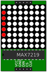 There is one byte per column of the 8×8 matrix i.e. 8 bytes. One byte signifies which of the 8 LEDs in a column should be turned on.
 0x3E in binary form is 00111110 and every bit represents the state of one LED. So, the first LED and the last two will be OFF while the others will be ON. Again, the notion of “first” and “last” of course depends on the orientation of the matrix but as long as all characters are defined consistently it doesn’t matter. 0x3E on the matrix will look as shown on the left.
Moody, cycling through smileys
Moody is a simple program that declares 3 smileys and an array which contains all of them. It shows how to initialize NodeMCU SPI for the MAX7219 8×8 LED matrix and how to cycle through the smileys array and display one face after the other in a loop.
This file contains bidirectional Unicode text that may be interpreted or compiled differently than what appears below. To review, open the file in an editor that reveals hidden Unicode characters.
Learn more about bidirectional Unicode characters
| MAX7219_REG_NOOP = 0x00 | |
| MAX7219_REG_DECODEMODE = 0x09 | |
| MAX7219_REG_INTENSITY = 0x0A | |
| MAX7219_REG_SCANLIMIT = 0x0B | |
| MAX7219_REG_SHUTDOWN = 0x0C | |
| MAX7219_REG_DISPLAYTEST = 0x0F | |
| happy = {0x3C, 0x42, 0xA5, 0x81, 0xA5, 0x99, 0x42, 0x3C} | |
| frown = {0x3C, 0x42, 0xA5, 0x81, 0xBD, 0x81, 0x42, 0x3C} | |
| sad = {0x3C, 0x42, 0xA5, 0x81, 0x99, 0xA5, 0x42, 0x3C} | |
| faces = {happy, frown, sad} | |
| function sendByte(reg, data) | |
| spi.send(1,reg * 256 + data) | |
| tmr.delay(50) | |
| end | |
| function displayFace(faceIndex) | |
| local face = faces[faceIndex] | |
| — iterates over all 8 columns and sets their values | |
| for i=1,8 do | |
| sendByte(i,face[i]) | |
| end | |
| end | |
| function setup() | |
| spi.setup(1, spi.MASTER, spi.CPOL_LOW, spi.CPHA_LOW, 16, 8) | |
| sendByte (MAX7219_REG_SHUTDOWN, 1) | |
| sendByte (MAX7219_REG_SCANLIMIT, 7) | |
| sendByte (MAX7219_REG_DECODEMODE, 0x00) | |
| sendByte (MAX7219_REG_DISPLAYTEST, 0) | |
| sendByte (MAX7219_REG_INTENSITY, 9) | |
| sendByte (MAX7219_REG_SHUTDOWN, 1) | |
| tmr.stop(0) | |
| end | |
| — changes the face every two seconds cycling through the array of faces | |
| function moody(i) | |
| faceIndex = (i % 3) + 1 | |
| displayFace(faceIndex) | |
| tmr.alarm(0, 2000, 0, function() | |
| moody(faceIndex) | |
| end); | |
| end | |
| setup() | |
| moody(0) |
I get the following error:
Can you help me
Nodemcu V1 nodemcu float 0.9.6-dev_20150704
Read the article again. It says you need the NodeMCU from a current dev branch. See http://frightanic.com/computers/build-nodemcu-firmware-for-the-esp8266/.
How to use more than one matrix ? How can I select haow many matrix I’m using ?
I don’t have a working example but see this https://github.com/nodemcu/nodemcu-firmware/issues/50#issuecomment-149117076 and this https://github.com/nodemcu/nodemcu-firmware/wiki/nodemcu_api_en#spiset_mosi.
In case you’re still interested and haven’t built it yourself in the meantime there’s hope…See http://frightanic.com/iot/max7219-library-nodemcu-making/
I try to write lua code to show the ds18b20 temperature on one piece 8×8 MAX7219 with a NodeMCU. That will take me some days, I am new to lua… I searched the internet to see if someone already made this, but did not found it.
A ticker or displaying the numbers of the temperature fast after each other.
Ideas are welcome!
Hi! I know this hasn’t been commented on in a bit but is there a way to modify for a 8×8 Matrix that only has 4 pins and not 5? I’m new to lua! 🙂
@todd: Could it be that this is an I2C device, not a SPI one? The labels next to the pins might tell you.
Great Blog. Thanks
My question: Is it possible with the same code to arrange the MAX7219 such that we get a say 16 x 16 or 24 x 24 or 32×32 square which can display these Emoji in a bigger size?
Please clarify & guide on how to approach. Thanks in advance.