In this post I’ll show you how to build a LoRaWAN gateway for The Things Network. While I could talk about what LoRaWAN is or why I think it’s essential that the IoT world fully embraces it I’ll refrain from doing so. Accordingly I won’t be introducing The Things Network (TTN) in this article either. It’s my assumption that readers who end up here did so because they’re interesting in actually building a LoRaWAN gateway for The Things Network rather than learning about core concepts. Still, please let me know if my assumption is wrong and I might publish an additional article or amend this one.
My requirements
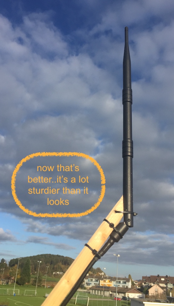
The location of a LoRa gateway is much more essential for its ubiquity than for example its antenna. In particular you want the gateway to be outside and unshielded from obstacles. Ideally it has an unrestricted 360° “view”. Hence, the taller the structure you place it on the better.
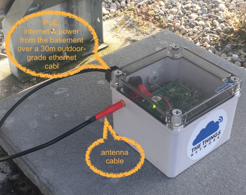
For those reasons I wanted to place mine on the roof of my house. As there’s neither WiFi nor electricity available up there I want to feed both data and power over a single Ethernet cable using PoE. Furthermore, to keep track of a few health indicators the gateway must be equipped with some kind of environment sensor.
Bill of material
If the BOM below looks long and intimidating then that’s because it is – at first sight. However, depending on how much of an electronics nut you are you may have some of the components laying around your desk already. This was one of my first serious electronics project and I learned quite a bit. Once you’ve got all the parts ready though it’s not really complicated. Certainly if I can do it so can you!
For some of the components there are alternatives which I discuss in the respective sections below.
Gotcha! LoRa operates at different frequencies in different regions of the world. You need a chip and antenna that fits your location!
| Region | Frequency |
|---|---|
| Europe, Russia, Africa | 433 and 863-870 MHz |
| America | 902-928 MHz |
| China | 470-510 and 779-787 MHz |
| Australia | 915-928 MHz |
| Southeast Asia | 923 MHz |
| Korea | 920-923 MHz |
Check The Things Network frequencies-by-country page for details.
Sourcing the parts from different local and international suppliers was a major headache for me. Let me know if you are interested in buying a kit from me!
- Electronics
- Raspberry Pi 2 Model B (plus SD card for OS), €40
- IMST iC880A-SPI LoRaWAN concentrator for 868MHz, €155
- Backplane to connect concentrator to RaPi, €50 for 4
- Antenna
- Case
- Power/data supply
- PoE kit, €30
- 3 Ethernet cables
- 1 to connect router and gateway, length depends on situation on-site
- 2x 15cm/6” flat-design or slim line patch cable for within enclosure, €10
- Miscellaneous small parts
- 2.54mm/1” female pin headers (~60), €1
- 2-pin terminal block 5mm pitch, €1
- 2x 2 male pin headers with jumpers
- M4 spacers
- Optional sensor
Build a LoRaWAN gateway for The Things Network
Soldering components to backplane
The first step is to connect all electronics components. That is what the backplane is for. The idea is that you plug in the RaPi on one side and the concentrator on the other. Therefore, you need to solder the following components:
- 2×20 female pin headers to the bottom of the backplane, you’ll plug the RaPi in here.
- 1×20 plus 2×3 female pin headers to the top of the backplane, you’ll plug the concentrator in here. The 2×3 female pin headers go where it says “ic880a” on the backplane.
- 1×4 female pin headers to the left most I2C connector of the backplane.
- 2-pin terminal block where it says “DC Input”.
- 2×2 male pin headers for the jumpers at “JP1” and “JP2” and close both (i.e. add the jumpers).
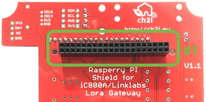
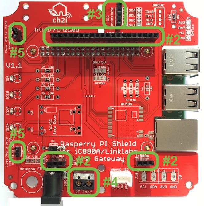
The photos above are originally from https://github.com/ch2i/iC880A-Raspberry-PI#boards (designer of the backplane). Ignore the DC barrel jack in photos. I soldered it to the backplane just in case but ended up not using it.
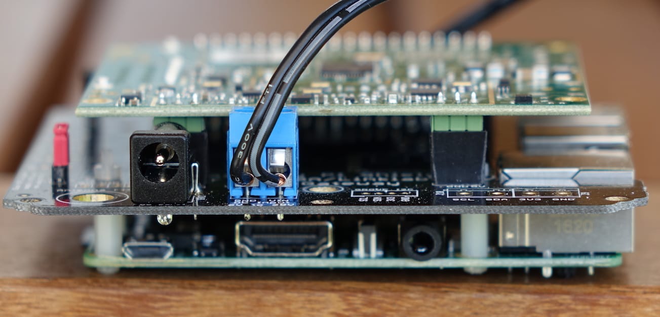
Eventually plug the three core components together to form a RaPi-backplane-concentrator PCB stack. Also, plug the BME280 breakout into the soldered pin headers.
WARNING Don’t ever power up the concentrator when the antenna is NOT connected!
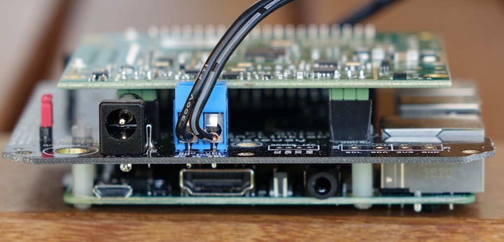
PCB stack: RaPi, backplane, concentrator (from bottom). On the backplane you see (from left): jumpers, DC barrel jack, 2-pin terminal connectors. 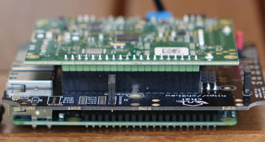
PCB stack from opposite direction. First element in viewing direction is the 4-pin I2C connector.

Alternatives to this backplane
The backplane I used here is extremely versatile and supports pretty much all configurations and add-ons you can think of – the fully monty so to speak. There are at least two alternatives that are simpler but they come at the cost of flexibility:
- Simple backplane from Gonzalo Casas: https://www.tindie.com/products/gnz/imst-ic880a-lorawan-backplane-kit/
- 7x dual female jumper wires as seen here: https://github.com/ttn-zh/ic880a-gateway/blob/spi/images/mounted-boards.jpg
Installing and configuring TTN software
The mother of all TTN gateway how-tos contains lots of manual steps. While it may be helpful for some to understand what you’re actually doing my friend Squix and I felt we could do better – for us and for everyone else building their own gateways.
It’s no secret that containers like Docker have been hip for quite some time. Naturally we thought it should be possible to provide a Docker image that contains the entire TTN software stack on top of Raspbian (the Raspberry Pi OS). And so we did.
Our manual contains an easy recipe but the following outline should give you an idea how simple it is:
- First of all download and save the OS onto the SD card.
- Then adjust a few Raspberry Pi setting once it has booted. Again, don’t power the concentrator when the antenna is not connected!
- Finally run the Docker container with a single command and pass a few gateway parameters to it
In addition to that this gateway needs I2C enabled on the Raspberry Pi for the BME280 sensor. Thus you do sudo raspi-config then 5 Interfacing Options > P5 I2C > Yes.
Upload sensor data to ThingSpeak
Possibly this warrants a post of its own but it fits in really nicely here…
If you build a LoRaWAN gateway for The Things Network you’ll want to be able to remotely check on its health. Hence you need sensors that measure certain parameters. However, as I had no intention to extend this outdoor gateway into a weather station I only needed sensors inside the enclosure. The BME280 measures temperature, humidity and barometric pressure. If you combine the first two with the Raspberry Pi CPU temperature you can assess easily if the hardware is running in a healthy environment.
Even though the IoT data collecting platform ThingSpeak has stagnated recently I upload my gateway sensor data there. At least it does the job and I’m familiar with its API.
- First and foremost I had to fix pip. Unfortunately I don’t know why it’s broken on the Raspian I’m using.
pip --versionreturned “ImportError: cannot import name IncompleteRead” which appears to be a popular question on Stack Overflow. If I remember correctly I fixed it by reinstalling pip:sudo apt-get remove python-pipwget https://bootstrap.pypa.io/get-pip.pysudo python get-pip.py- reboot the Pi
- Then I followed a nice tutorial on how to read data from a BME280 with Python.
sudo apt-get install -y python-smbus i2c-toolswget https://bitbucket.org/MattHawkinsUK/rpispy-misc/raw/master/python/bme280.py- Test run
sudo python bme280.py
- Then I installed the ThingSpeak Python library as per its manual:
sudo pip install thingspeak - Finally, the small script to wrap everything up:This file contains bidirectional Unicode text that may be interpreted or compiled differently than what appears below. To review, open the file in an editor that reveals hidden Unicode characters. Learn more about bidirectional Unicode characters
import thingspeak # from https://thingspeak.readthedocs.io/en/latest/ import bme280 # from https://www.raspberrypi-spy.co.uk/2016/07/using-bme280-i2c-temperature-pressure-sensor-in-python/ # return the Pi CPU/GPU temperature in degree Celcius; it's a SoC and thus there's no need to read both, see # https://www.cyberciti.biz/faq/linux-find-out-raspberry-pi-gpu-and-arm-cpu-temperature-command/#comment-796904 def get_temp(): with open('/sys/class/thermal/thermal_zone0/temp', 'r') as infile: return float(infile.read()) * 1e-3 ch = thingspeak.Channel(275145, "*********", "*********") temperature, pressure, humidity = bme280.readBME280All() data = {"field1": temperature, "field2": humidity, "field3": pressure, "field4": get_temp()} # print(data) ch.update(data)
Preparing the enclosure
The initial idea was to screw the PCB stack to the bottom of the enclosure then somehow put the PoE splitter on top. So, I drilled two holes for the antenna and the waterproof RJ45 adapter in one corner of the enclosure. Then I prepared some scrap wood because I didn’t have the right brass spacers standoff. At that point the enclosure looked like this:
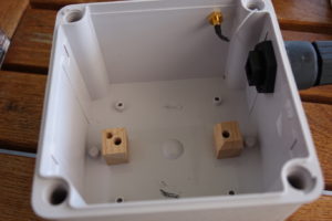
I’m an engineer and I remember enough uni physics to understand the correlations between humidity, temperature and pressure. However, I had zero experience building outdoor enclosures. I didn’t understand the degree to which those effects would impact my installation thus. For a brief moment I thought about cutting a square-inch “window” into the enclosure and then cover it with a Gore-Tex membrane. I would have harvested it from an old outdoor jacket. Eventually I didn’t but we’ll come back to that in a minute.
Fast forward two months. The gateway had been online for several weeks and I had been monitoring, slightly concerned, rising humidity levels. After a sudden surge during a heavy thunderstorm I climbed to the roof to check on my baby. Here’s what I found:
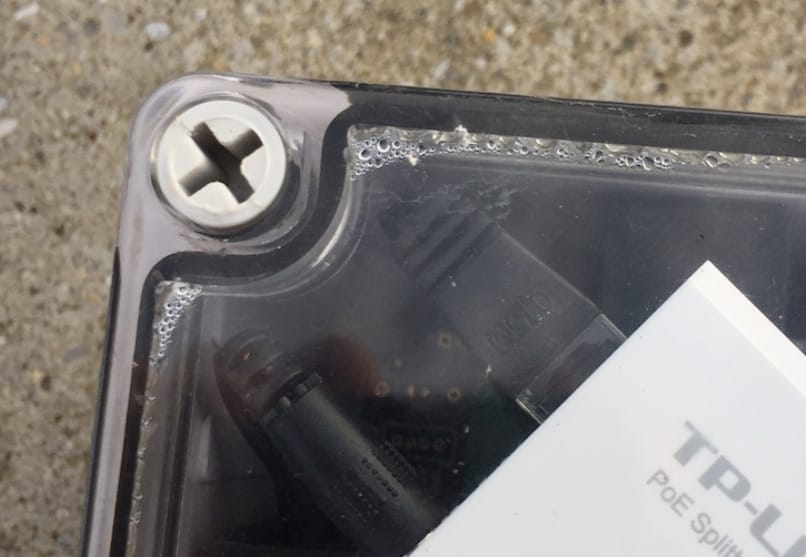
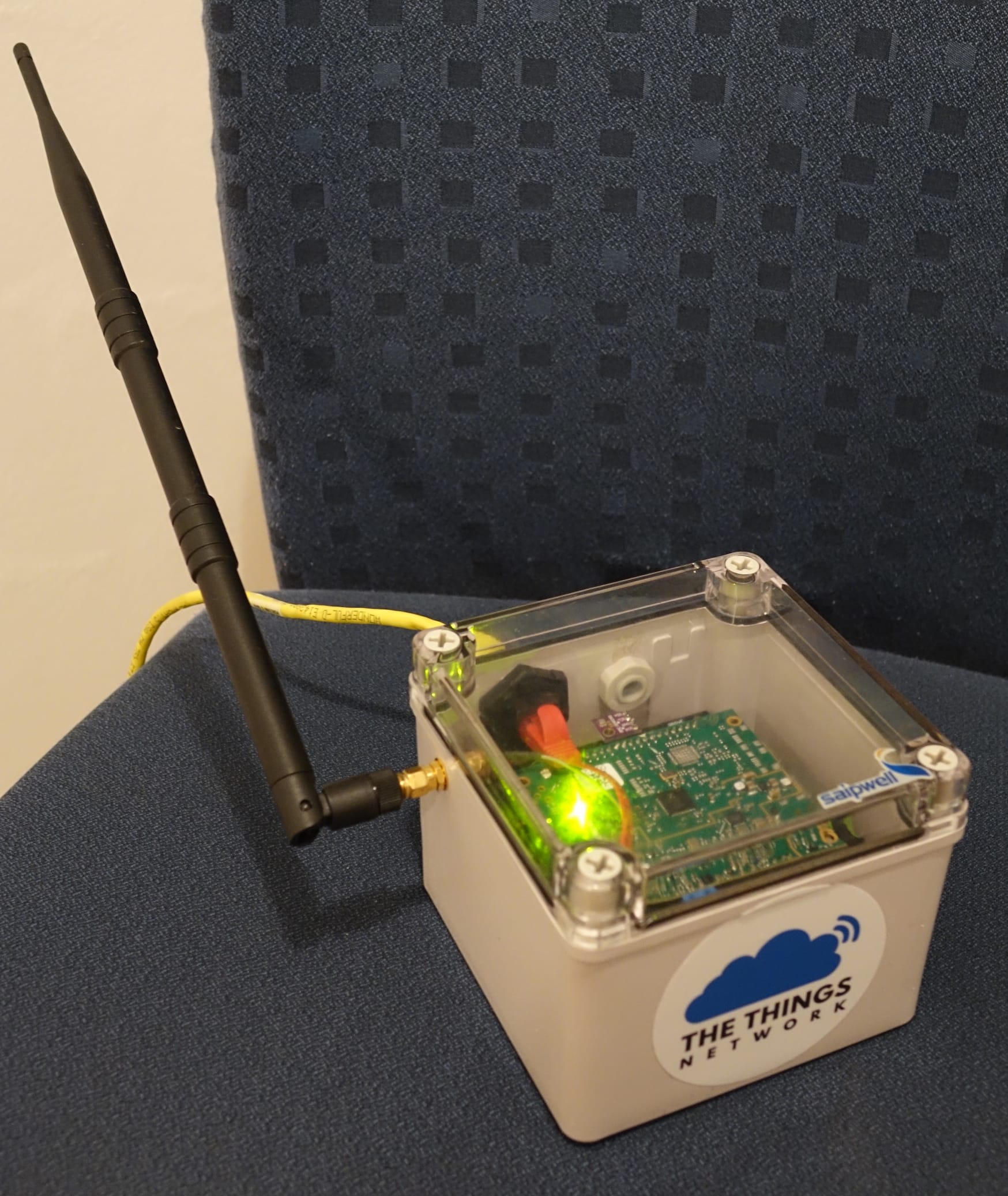
Condensate at the ceiling of the enclosure. Transparent covers are really helpful… 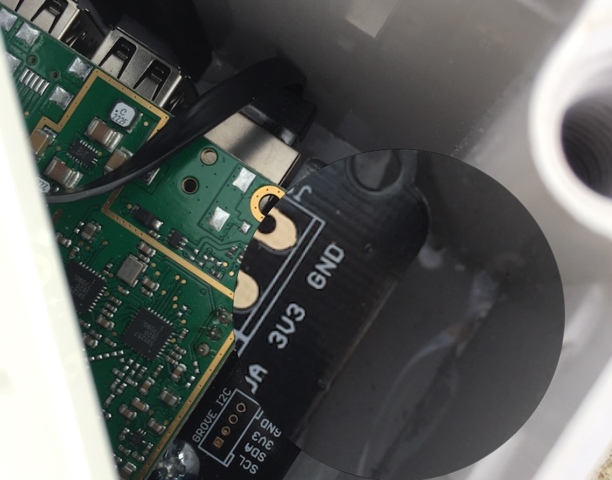
Accumulated condensate at the bottom of the enclosure.
So, clearly this meant my enclosure wasn’t ready for months and years of unattended exposure to the elements. Usually this means back to the drawing board. In my case, however, this meant back to internet research.
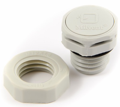
I read a few articles online and learned that the solution to this problem be supposedly simple. Just drill another hole and insert a pressure vent (aka pressure compensation device) it was suggested. A pressure vent is a valve with a waterproof membrane inside. Maybe you remember my initial Gore-Tex idea?
So, this little thing on the right makes all the difference.
Final assembly
As with the enclosure itself the initial assembly idea was a failure and in hind-sight it was an obvious mistake. However, I’ll spare you the details to get to the point. Of course anything discussed below largely depends on the selected enclosure. Just talking about mine here.
Eventually the general idea was to place the PoE splitter somewhat diagonally on the bottom of the enclosure. This means that some of the “bumps” there need to be removed. Then I placed it between the two bumps that hold the M4 screw threads. Next I cut the DC power cord from the PoE splitter to about 20cm, stripped the isolation on that end and feed it into the terminal block on the PCB stack.
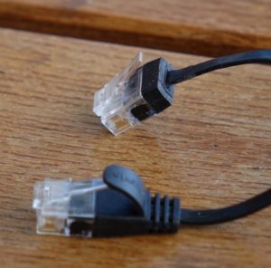
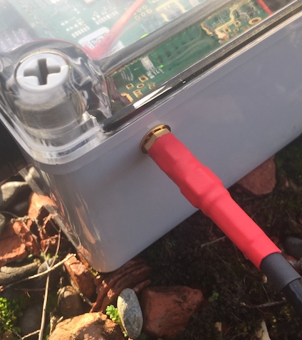
As the enclosure really is a tad too small I carefully(!) stripped some plastic from the one ethernet cable that’ll be plugged into the Raspberry Pi. Finally everything inside the inclosure can be plugged together. Ethernet A (left) goes from the Pi to the PoE splitter. Ethernet B goes from the splitter to the RJ45 connector in the enclosure wall, and the power cord with the DC jack goes from the splitter to the backplane.
To secure everything two M4x40 screws go from the backplane to the enclosure bottom. As the PoE splitter is thus sandwiched in between the enclosure and the PCB stack it’s wise not to tighten those screws too much.
Don’t forget to plug the antenna pigtail into the concentrator before you switch everything on!
Closing remarks
I hope I managed to give you an idea how to build a LoRaWAN gateway for The Things Network. While working on this post I realized that writing instructions is not something that comes naturally to me. The fact that I felt it necessary to include some of the failures of the first version of my gateway certainly doesn’t contribute to readability, I know. Therefore, I was wondering more than once whether to completely dump those paragraphs. Also, as a reader I believe doing this in a video may be a lot more instructive. I might do that eventually – should I build another gateway.
So, when will you build a LoRaWAN gateway for The Things Network and support the community?
Hello Marcel,
Where did you buy the pressure vents? The link you attached in the description points to a purchase of 100 pcs. I am not in the gateway building business, so I would need 3 pieces at maximum. Could you recommend a purchasing source?
Regards,
Gabor
I know firsthand that depending on where you live it may be hard to source those parts. It starts with the name; they’re called different names by different manufacturers in different parts of the world. I’ve seen “pressure vent”, “pressure compensation valve”, “vent plug”, “protective vent”, “Gore vent” and others.
Did you try ebay and Amazon? I found some on taobao that are sold individually at https://world.taobao.com/item/549105357696.htm. In Switzerland you could get them at https://www.bastelgarage.ch/index.php?route=product/product&product_id=67 for example. Furthermore, Takachi from Japan sells lots of different enclosures and pressure vents (http://www.takachi-enclosure.com/data/p_06ip65plastic.html) through their network of distributors, see http://www.takachi-enclosure.com/data/contact.html.
Btw https://www.gtteurope.co.uk has a pretty cool enclosure designer for your specific needs. Actually, the idea is cool, the implementation a little less so.
Hi, Marcel, really good article and including the mistakes you made was really helpful. How long did it from start to finish? I lost track. A timeline would be really helpful. I assume that this project was a part-time activity, is that a valid assumption? If so could you try to express any timeline as such?
Thanks for the praise Antony. The longer I look at the article the less satisfied I am with it to be honest. I think I should have feazed it into two separate articles. One would be a “emotionless” step-by-step instructable. The other, being based on the former, would talk about the history, timeline and mistakes I made building my first gateway (and first outdoor enclosure).
Yes, this was a hobby project that dragged on for months. It was sitting idle several times for weeks and months. Sometimes that was because I was waiting for parts to arrive and sometimes it was because I couldn’t muster time and/or energy to push it forward. At this point it’s impossible for me to reconstruct a timeline that’d be accurate enough to be helpful, sorry.
I understand those issues. I’m not sure going back to it is the best use of your time either though!
Hi Marcel!
Thank you for this tutorial, it was really hepful.
The iC880A costs currently 119€.
http://shop.imst.de/wireless-modules/lora-products/8/ic880a-spi-lorawan-concentrator-868-mhz?c=7
Regards
Pedro
Have you encounter temperature issue? How is temperature increase in summer?
On ThingSpeak I’ve so far collected some 47k readings over the course of roughly a year. Summary:
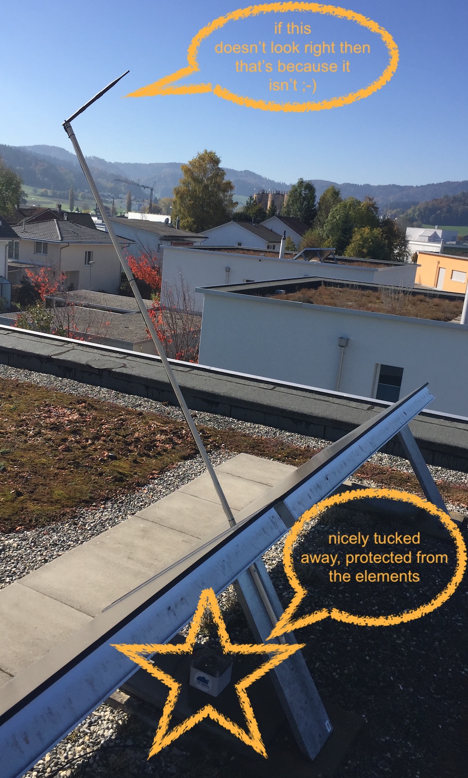
The gateway is placed on the roof of my house but without direct exposure to the sun. It sits in the shade of the solar panels and is thus a bit protected from the elements. The antenna is detached over a 3m coax cable for better RF reception.
The outside temperature ranged from roughly -18°C to +35°C in the past 12 months.