The Lovebox is a project I learned about through a Make: magazine article from 2019. A reader notified ThingPulse – of which I’m a co-founder – because the project’s Arduino sketch relies on an open-source display driver provided by ThingPulse.
I was immediately intrigued as the project involves electronics, software and classical woodworking. As a born-and-breed cabinet marker, later turned software engineer, I loved that building it would allow me to combine many of my interests. Also, I saw a good reason to put the new (used) bandsaw I had recently added to my still scarcely equipped workshop to good use. Not to mention the fact that for once I happened to have all the required hardware, both wood and electronics, at home already. The only thing missing yet is mirror/darkening film to build a magic mirror on top of the OLED display.
This is not a full-blown instructable. Rather, I’ll publish a few photos of my implementation and add a few notes. All credits go to Lisa Ihde who created the project and who wrote the Make: article. Please read her project description at http://lisaih.de/Lovebox/.
Basic idea
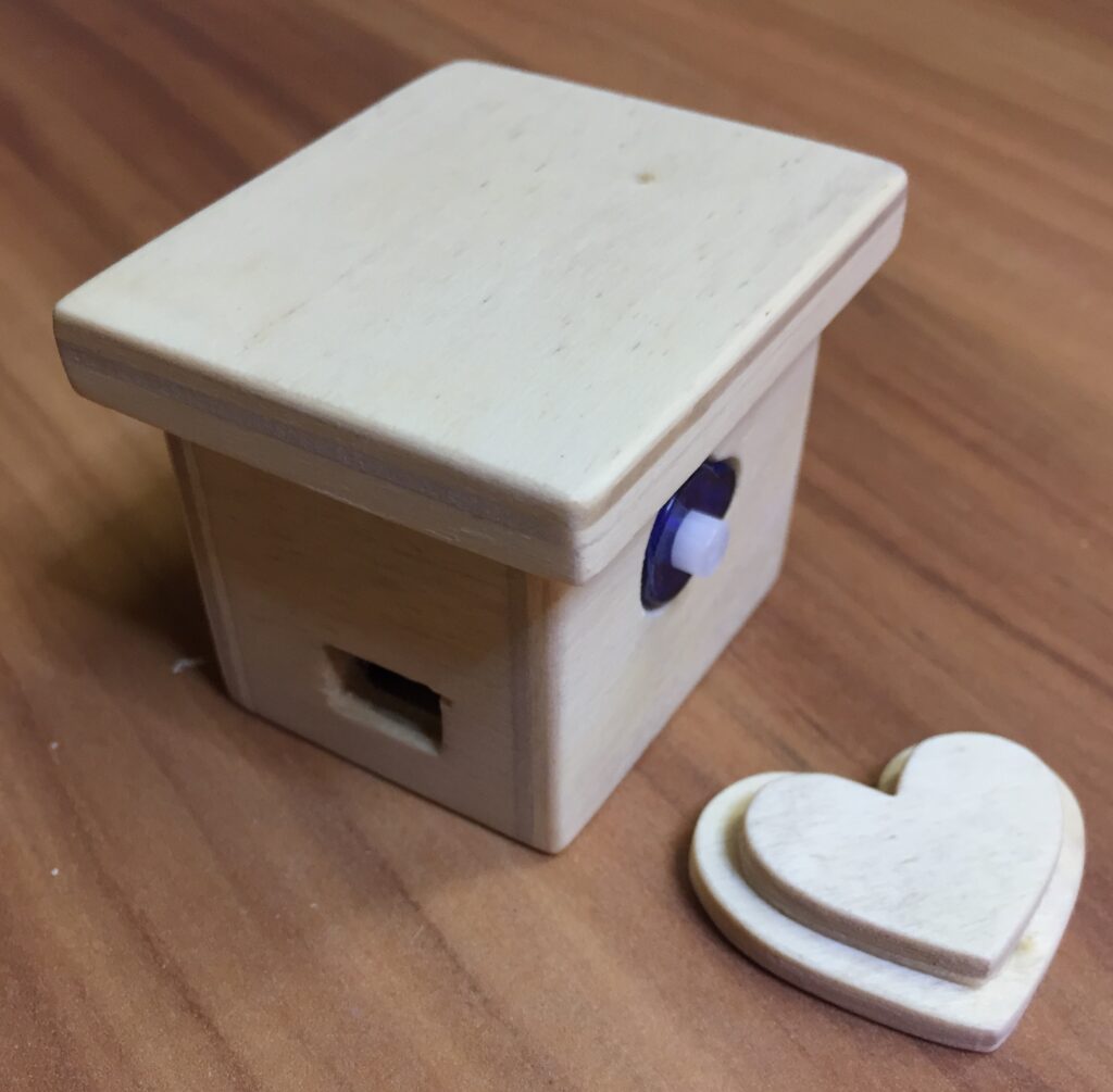
When the Lovebox receives your message for a loved one, the heart wiggles until she/he lifts the lid and reads the message on the display hidden inside the box.
The initial app implementation polls a GitHub Gist for new content. If it sees a new message (text or image) it displays it and sets a servo in motion to which the heart is attached. When the lid is opened a photoresistor (acronymed LDR for Light Decreasing Resistance, or light-dependent resistor) registers the extra light in which case the app stops the servo.
The electronics
Very few components are required and luckily I had all of them at home already when shortly before Christmas I decided to build a Lovebox for my wife.
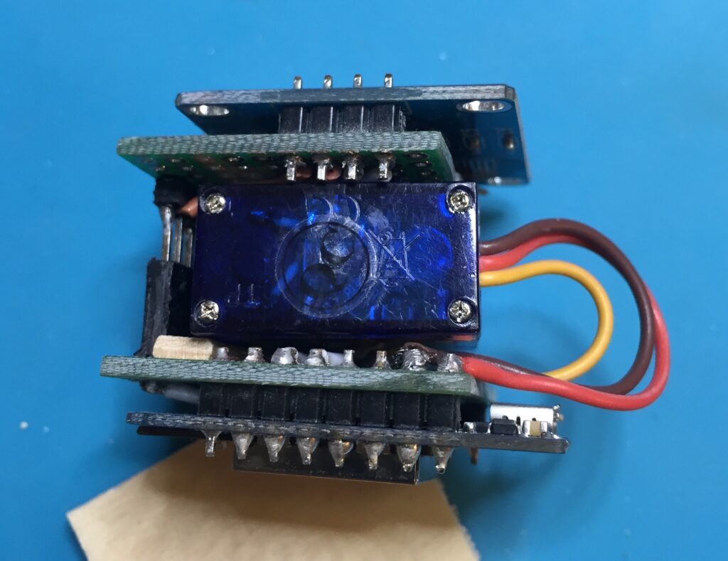
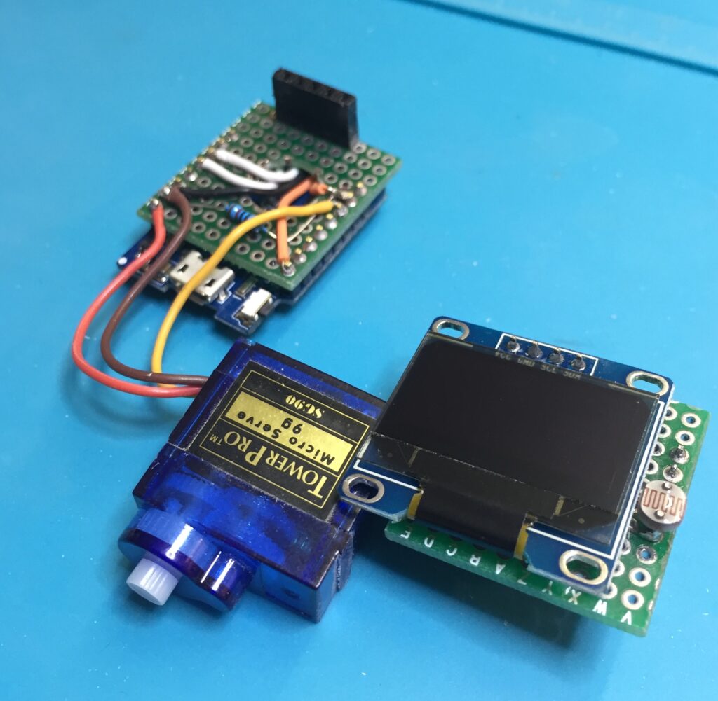
In her project Lisa sandwiched the servo between a WeMos D1 mini ESP8266 and the 0.96″ OLED display. Both sit on a perf board of their own. It’s a fairly logical stack. However, in hind sight I wonder if it wouldn’t be simpler to solder the display directly to the back of the D1 mini.
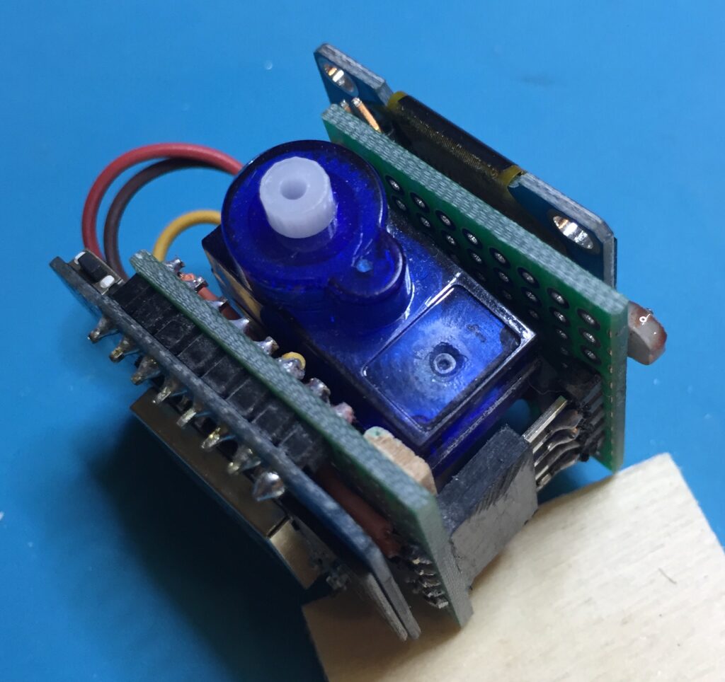
MCU and servo
From an earlier project my WeMos D1 mini already had pins soldered to it. So, first I soldered it a perf board into which I had previously drilled a ~10mm hole in the center. That allowed me to feed the wires from the MCU pins to the back side of the female pin headers on the side of the board.
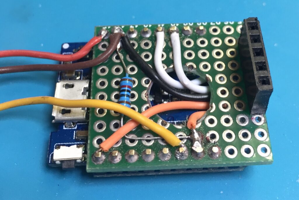
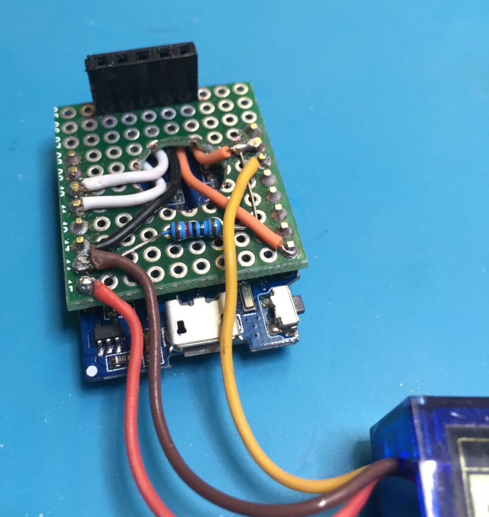
This section obviously involved many repetitive steps. Cut a wire to length, strip both ends, tin them, bend them to an open loop, place the ends around a pin, solder them. At the end I filed down the pins to minimal length.
While soldering those wires I really came to appreciate the two most favorite recent additions to my workshop (links go to Amazon): the Jokari automatic wire stripper and the Goobay magnifying lamp – brilliant pieces for the workbench, both of them.
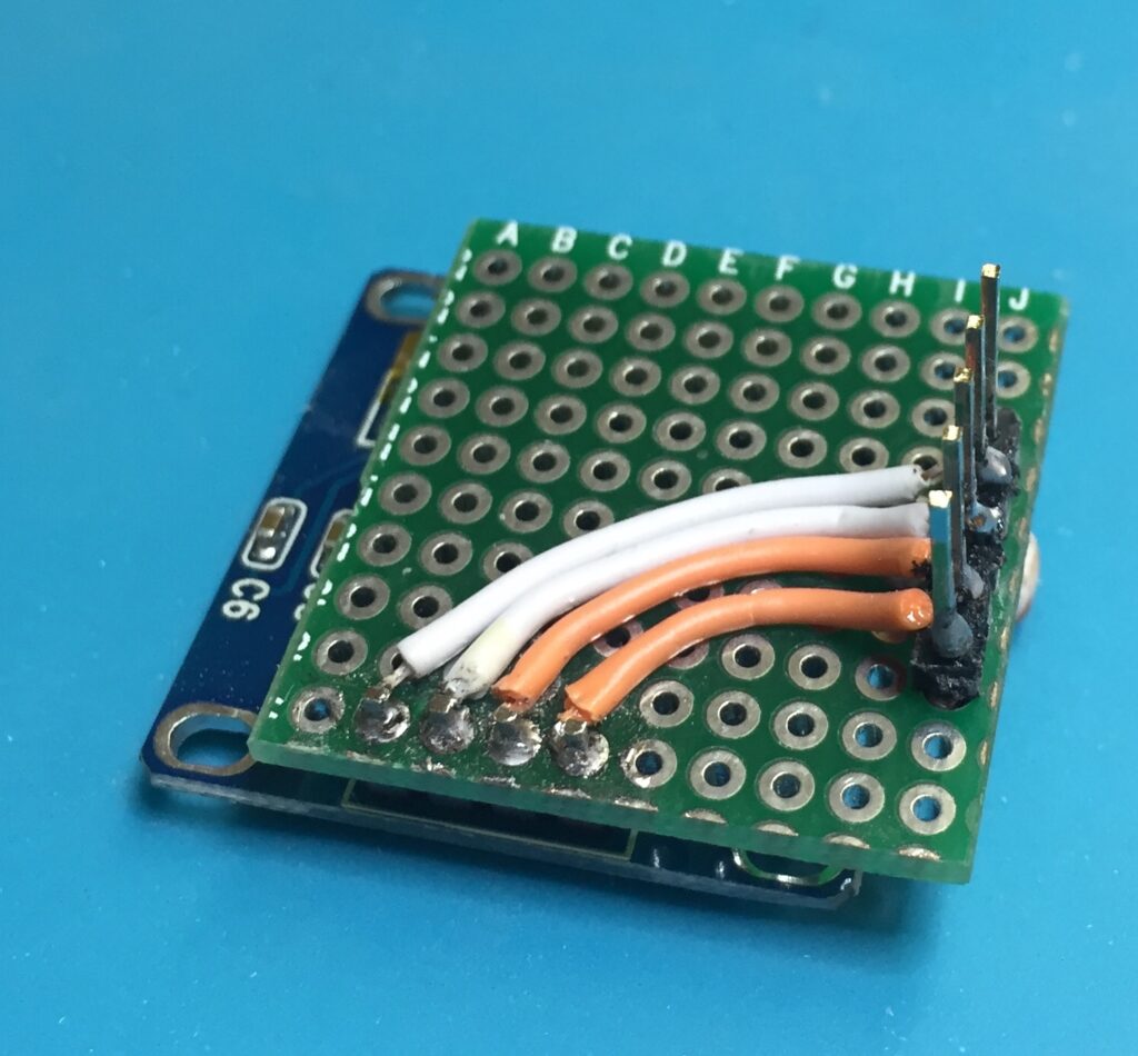
Display and LDR
Again, I first soldered the 0.96″ OLED display, which came with pins attached, to a perf board. Then I added a row of 5 extra long male pin headers and the LDR. Finally I connected the display pins in a somewhat bizarre way with the connector pins. I’m sure there’s a more straightforward way to do it. However, as is obvious from the pictures I’m a real electronics rookie.
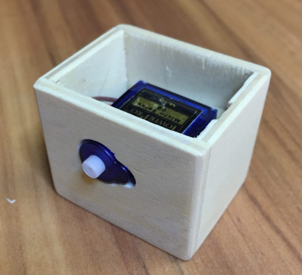
The woodwork
For her original project Lisa apparently used 3mm plywood. What I had available was 4mm plywood. That gives the lid of the box a slightly more chunky look but works otherwise just fine. Also, while Lisa had a laser cuter available I had to rely on solid and honest craftsmanship. Every piece small, everything a bit fiddly. Oh, how I loved that! After I sanded the outside (see below) I treated the plywood with natural wood oil and painted the heart with acrylic paint.
The software
Before I got to work on the electronics I connected the components on a breadboard in tinkered with the original code. Rather quickly I decided to create a fork to clean up the code a bit. The original code:
- Doesn’t write anything to the serial console.
- Stores the message sequence number and read state in EEPROM. I didn’t see much value in that.
- Polls the GitHub Gist in
loop(). That’s crazy; no one needs such high frequency. I added a configurable fetch interval in between which the MCU does “nothing”. - Does not have Arduino IDE-friendly directory structure and file names.
- Uses SSL server certificate fingerprint for the SSL/TLS handshake. That is not desirable as you need to change it in your source code every time the server certificate changes (i.e. every couple of months). My code uses the CA root certificate instead that is valid until 2031.
The most obvious major flaw in my opinion is an architectural one and I haven’t “fixed” it yet: rather than polling the GitHub Gist for new messages – however infrequently – the more sensible choice would have been an MQTT pub-sub model. CloudMQTT for example offers a free-tier and also has a nice web UI to publish messages without the need for a dedicated client.
Update 2021-11-28: MQTT is now supported by my Lovebox application. The README at https://github.com/marcelstoer/Lovebox describes how.
The feedback
Oh, you want to know what my wife said? She absolutely adores it and is proud to own something unique, something you can’t buy anywhere. But…she wouldn’t mind a slightly larger display. Frankly, I wouldn’t mind either. As larger OLEDs are fairly expensive I might as well use an e-ink display instead should I ever build another Lovebox.
Hello, I just made this project last week for my girlfriend. She LOVED it- thank you so much for the insight. However, I just realized today it cannot connect to her university WiFi (eduroam), at least I don’t know how to get it to do so when it is not as simple as SSID and password. Do you know if it is possible? And if not, could you recommend ethernet-capable devices which may work for this project (albeit bigger). I can remake one, but I am quite a rookie to this field and would love some advice.
Thank you again – this is such a neat project.
Any luck on figuring this out? I’m making one for my girlfriend this Christmas while she’s back from covid but when that passes she’ll need it in her dorm as well.
I began going down the Ethernet shield route, but hit a road block trying to get it connected to a an https server (as is done in the arduino code given in this tutorial). It seems the ethernet library doesn’t support secure connections. I’m very new to this, so I’m not sure where to go from here.
Due to missing support in the underlying SDK from Espressif this won’t work (according to the sources I checked). How about making the device connect to her mobile phone – on which she would have to enable tethering i.e. personal hotspot.
That could be a work-around, thank you for the suggestion!
Keep in mind this will only work if her phone isn’t connected to WiFi itself. At least on iOS the phone’s personal hotspot turns off as soon as you connect the phone a WiFi network.
So I have just finished breadboarding everything and got it working with Lisa’s code but I cannot get it to work with your branch. It seems to be stuck “Fetching message . . .” this repeats without end even after updating the gist. The gist path and Wi-Fi credentials are identical on both so I am lost on what the cause could be.
Hi there! Love this project and the enhancements you made to Lisa’s already awesome code. I was wondering if you had made any progress on using a MQTT message broker. It appears CloudMQTT unfortunately got rid of their free plan so I was wondering if you had any suggestions on others to use and how to implement that in the code
Adding MQTT support would be really simple using https://pubsubclient.knolleary.net/. I was about change my code a couple of times already but I’m still hesitant. I feel it would raise the bar a bit for certain users as you then also need an MQTT client of sorts to publish messages. As for public brokers there’s https://myqtthub.com/en and https://www.emqx.io/mqtt/public-mqtt5-broker that appear to be offering a free tier.
Implemented the MQTT option (now the default) over the weekend. The README at https://github.com/marcelstoer/Lovebox describes how.
Hi, how would you go about using an e-ink display for this? Is it exactly the same but just replace the display? This will be the first electronic thing I’ve made myself, thanks for your time 🙂
I wish it were that easy 🙂
First, e-Ink/ePaper displays usually have FPC connectors that require adapter boards if you want to connect them to standard ESP8266/ESP32 development boards. Example: https://www.buy-lcd.com/products/154-inch-eaper-display-high-resolution-200x200artial-refresh-fast-speed-gdew0154m09
Second, you need a display library that supports the particular display such as https://github.com/ThingPulse/minigrafx/ or https://github.com/ZinggJM/GxEPD2 or maybe https://github.com/Bodmer/TFT_eSPI.
Hence, if this is your 1st IoT project I suggest you go with the OLED display first.
Hi im looking to make this for my boyfriend but I don´r have any hardware or computer skills. Do u have any soures/books/websites where I can read up a bit about the tecniques used in this project and make my attempt. I especially don’t understand how all the materials end up stacked.
Thank you,
Rita Mesquita
Woah, I admire your determination! And I wish you lots of luck and endurance in the pursuit of your goal. Let us know how it goes.
If you are inexperienced in all the fields required for this project (wood working, electronics, programming) then I assume this is a rather tough project to get started. However, there are ways to simplify the challenges. You could for example buy an off-the-shelve box instead of building your own. Also, things become a little easier if the Lovebox doesn’t need to be as miniature as the one I built here. A larger scale is more forgiving.
Depending on where you live the difficulties might start with sourcing the (right) components for this project. Let me know if you need help with this.
As for tutorials I am a little lost at where to start. Maybe watch a few videos on how to solder components around a WeMos D1 Mini (the WiFi micro controller used here).
Hi everyone, I’m currently trying to get this project working to gift it to my girlfriend but ran into some troubbles.
My OLED screen show the <3 Lovebox<3 text at startup but schows nothing afterwards. The servo begins to spin and stops when the light sensor detects light but no massages show up on the OLED.
Does someone know what could possibly be wrong?
What do you see on the serial console (e.g. the one included with the Arduino IDE)? I suspect writing to the OLED is not the problem as the startup message wouldn’t otherwise be displayed. Might be that the connection to the host you fetch the messages from cannot be established.
Comments here are not well suited to start a remote debugging/analysis session. Do you happen to be subscribed to the forums at esp8266.com or StackOverflow? We could then move this discussion there.
Hi and thank you for your response. Unfortunately I am not subscribed to these forums.
When I look into the seriel console there are just questuonmarks appearing.
Ok, then I suggest you do and post there so that a global community of like-minded people can help you.
I am having the same issue. I actually had multiple parts laying around and built a separate new project to test and get this working. My device spins the servo for a second on the first official flash but then is stuck on <3 Lovebox <3. I have confirmed it connected to my wifi. Did you have any luck? Although my device does not spin when exposed to light etc.
hello, i built the love box but unfortunately he love box is not refreshing. when i change the message on gisthub, i need to restart the arduino so the new message can appear. Can someone help me find a solution ?
Hi! Try to change the fetchIntervalSeconds value from 60 to 5 or 10 for example. This value is the time interval in which it retrieves the message from github.
Hello, I am wanting to make this for my girlfriend as a Christmas gift and have run into an issue. I’m currently stumped because the program gets stuck on “Waiting for NTP time sync…” and just runs like that without ever syncing. I am not very familiar with NTP but I picked the one that should match my local time and the system clock on my PC. Is it just that I picked the wrong one and need to keep trying others or am I missing something else?
You normally won’t need to update the NTP server manually at https://github.com/marcelstoer/Lovebox/blob/master/lovebox.ino#L57. Just make sure you configured the ‘TIMEZONE’ variable in settings correctly. As your program appears to be stuck in an infinite loop at https://github.com/marcelstoer/Lovebox/blob/master/lovebox.ino#L62-L66 it’d be interesting to see what value ‘now’ has after fetching it through NTP. Maybe print that to the serial console? Also, I suggest you discuss this on Stackoverflow rather than through (a series of) comments here.
Yep, I was headed to Stackoverlow with the issue anyway but I figured I’d check to see if there was anything obvious I was missing. When I print ‘now’ to the serial console it just prints ascending integers starting at 0. I’m assuming this means it’s not properly connecting to the NTP server? I’ve had my ‘TIMEZONE’ variable configured to ‘TZ_America_Kentucky_Louisville’ since I’m in EST.
Hello, your article was very useful but i’m currently stuck with the proyect because when i try to run it it connect just fine to the internet but it keeps telling me that it failed to connect to github, i tried different gist but none of them seems to work, i hope you could help me
My device is stuck on <3 LOVEBOX <3
It connects to the wifi fine (verified through router UI)
How do i verify functionality?
https://docs.arduino.cc/software/ide-v2/tutorials/ide-v2-serial-monitor
Hello, I’m unsure if this is the optimal method to reach out, but I’m currently encountering a issue with the LoveBox. It seems to be consistently displaying “LoveBox,” and the Serial Monitor reports a failure to connect to GitHub. The device is connected to the internet, and time synchronization is working correctly. My speculation is that there might be an issue preventing it from reaching the GitHub servers at all (not just my GistFile), though this is just a uneducated conjecture on my part.
GitHub likely changed their root certificate and, therefore, SSL/TLS handshake fails. Try replacing the CA root cert as per https://randomnerdtutorials.com/esp8266-nodemcu-https-requests/#getting-server-certificate in settings.h.